 |
English | |||||||||||||||||||||||||||||||||||||||||||||||||||||||||||||||||||||||||||||||||||||||||||||||||||||||||||||||||||||||||||||||||||||||||||||||||
| Home page | Services | Past achievements | Contact | Site map |
||||||||||||||||||||||||||||||||||||||||||||||||||||||||||||||||||||||||||||||||||||||||||||||||||||||||||||||||||||||||||||||||||||||||||||||
|---|---|---|---|---|---|---|---|---|---|---|---|---|---|---|---|---|---|---|---|---|---|---|---|---|---|---|---|---|---|---|---|---|---|---|---|---|---|---|---|---|---|---|---|---|---|---|---|---|---|---|---|---|---|---|---|---|---|---|---|---|---|---|---|---|---|---|---|---|---|---|---|---|---|---|---|---|---|---|---|---|---|---|---|---|---|---|---|---|---|---|---|---|---|---|---|---|---|---|---|---|---|---|---|---|---|---|---|---|---|---|---|---|---|---|---|---|---|---|---|---|---|---|---|---|---|---|---|---|---|---|---|---|---|---|---|---|---|---|---|---|---|---|---|---|---|---|
| Page d'accueil | Services | Réalisations précédentes | Contact | |||||||||||||||||||||||||||||||||||||||||||||||||||||||||||||||||||||||||||||||||||||||||||||||||||||||||||||||||||||||||||||||||||||||||||||||
| Français | ||||||||||||||||||||||||||||||||||||||||||||||||||||||||||||||||||||||||||||||||||||||||||||||||||||||||||||||||||||||||||||||||||||||||||||||||||
| ||||||||||||||||||||||||||||||||||||||||||||||||||||||||||||||||||||||||||||||||||||||||||||||||||||||||||||||||||||||||||||||||||||||||||||||||||

|
Pressure is the analogue of voltage, and the amount of fluid (measured by its mass or its volume, assuming that its density remains constant) is the analogue for electric charge. The current is then measured as the amount flowing per second. One significant difference is that a flow of 6x10²³ electrons per second, which amounts to a massive current of about 105 amps (numerically, Faraday's constant), has a much greater effect than a flow of 18 ml/s of water, or 22.4 l/s of air. |

|
Current electricity was discovered around 1781, but the electron was not discovered until 1897. Between these two dates, researchers had to make an arbitrary decision as to which way they were going to nominate as the positive direction for current flow; unfortunately for us, they chose wrong. Ever since then, electronics engineers have had to train themselves to perform a seemingly absurd bit of mental gymnastics, designing their circuits with current flowing from positive to negative, while knowing that the particles themselves actually flow from negative to positive. This sounds like a trivial point, but it explains many oddities, such as in the naming of the electrodes of transistors (both bipolar and field effect), contrary to the arrows that are drawn on their schematic symbols.
One important distinction to make is between Electricity versus Electronics. If you have 6x10¹⁸ electrons flowing per second (one ampère), it can be used as a medium for transferring the energy from the generator to the consumer, or as a medium for transferring information from the input to the output. "Electricity" refers the former use (lights, heaters, motors, bench-top power-supplies), and "Electronics" to the latter. With electronics, the aim is minimise the energy, with only the laws of thermodynamics preventing us from reducing it right down to zero.
Resistors

|
Between the extremes of the perfect conductor, and the perfect insulator, the vast majority of materials act as resistors. One way of making a resistor is to use a long thin length of wire (just as a flow of water is impeded by being constricted down a long thin length of pipe, so too is a flow of electrons). |
Another class of material intermediate to conductor and insulator is the semiconductor. The difference between a semiconductor and a resistor is in the electrical conduction mechanism. In a resistor, the conduction electrons are impeded by the thermal jostling of the valence electrons of the rest of the material, and this tends to become worse as the temperature is raised. In a semiconductor, there is only a very limited number of conduction electrons available (hence its poor conduction), but more tend to be made available as the ambient temperature (and energy) is raised.
More importantly, the distinction is that resistive devices act as passive devices, whereas the majority of devices made from semiconductor materials act as active devices. The distinction is really one of what mathematical analysis tools are applicable for circuits that contain these devices. Rather than explaining this further, it is sufficient just to remember that resistors, capacitors and inductors (and transformers) count as passive devices, and that transistors and diodes count as active devices.
Capacitors

|
A capacitor can be made from two metal plates that are separated from each other by a thin layer of insulator. A good hydraulic or pneumatic analogue consists of a wide water pipe that has a rubber diaphragm across its cross-section. This well illustrates how a capacitor impedes a steady flow of current, but is a good conductor of alternating currents. |
Solenoids
|
Oested discovered that every wire that is carrying an electric current has a cylindical magnetic field around it, with the north-south orientation following "the cork-screw rule". For a parallel pair of wires in anti-phase, there are two magnetic fields squashing against each other. For a parallel pair of wires in phase, the magnetic fields combine down to one, since the squashed pair of fields would have adjacent field lines in opposite directions, which effectively cancel each other out to zero field at that point. For two turns of a winding look like a parallel pair of wires in phase, with a north pole and a south pole. For multiple turns of a winding look like a bar magnet, an electromagnet or solenoid. |

|
Inductors and Transformers
|

|


Impedances

|
Each of the three passive devices presents an impedance (measured in ohms) to the electron flow. For a resistor, the current is proportional to the voltage (Ohm's law, V=I.R). The constant of proportionality is the conductance (measured in mhos or siemens), and the resistance (measured in ohms) is simply the reciprocal of this. |
For an inductor, the back-voltage is proportional to the rate of change of current (V=-L.dI/dt). The constant of proportionality is the inductance (measured in henries). The impedance of an inductor is then proportional to this times the frequency of the alternating current, where the constant of proportionality is 2π (Z=2πfL). The admittance is just the reciprocal of this (measured in mhos, X=1/Z).
For a capacitor, the amount of fluid (the charge) that can be held is proportional to the voltage (Q=C.V). The constant of proportionality is the capacitance (measured in farads). The admittance of a capacitor is proportional to this times the frequency of the alternating voltage, where the constant of proportionality is 2π. The impedance is just the reciprocal of this (Z=1/(2πfC)).
Impedance is traditionally handled as a complex value, with resistance providing the Real part, and reactance (that is inductance and/or the reciprocal of capacitance) providing the Imaginary part. There are two reasons for doing this. One is that inductors and capacitors cause alternating voltages and their currents to become out of phase with each other, and indeed to tend towards being 90° out of phase. This is handled very conveniently using complex numbers (that is, using the complex mathematics as a tool that happens to model the behaviour well). The other reason is that inductors and capacitors both reduce the electrical energy entering the system by storing some of it for later use (hence the 90° phase shift). No energy is lost by a perfect reactance; it is just deferred. In a capacitor, it is stored in the electrostatic field; in an inductor, it is stored in the magnetic field. Resistors also reduce the amount of electrical energy entering the system, but they do so by releasing it as heat. Because of the second law of thermodynamics, we know that such energy can never be totally recovered. Hence, there is a sense in which resistors present Real impedance, while inductors and capacitors only present Imaginary impedance.
Circuit Analysis

|
Kirchhoff's current law assumes that each point in the circuit is a simple node, with the magnitude of the in-flowing currents summing to zero. If it turns out that there is more current entering the point than leaving it, then by definition it is not a simple node, but has a capacitance associated with it. By including such capacitors explicitly in the schematic, each one connected down to the reference voltage rail, returns the circuit to comprising just simple nodes. |
Kirchhoff's voltage law simply states that, if you navigate round a circuit diagram, calculating the change in voltage as you pass through each electronic component, you must get back to the original voltage whenever you arrive back at the same point again. The hydraulic or pneumatic analogue of voltage is pressure, and the same law applies. Analoguously, imagine a hiker renting a converted shepherd's hut for the week, each day going on a different hike, returning each night to sleep, whatever his route, he always crossed as many contours going up as he did going down, and ends up at the same height (above sea-level) again.
|
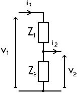
A potential divider involves applying a voltage, v1, across two impedances that are connected in series, Z1+Z2, thereby causing a current, i1, to flow. The junction between the two impedances is used as the output. In general, provided that i2 is kept negligibily small, it can be shown that v2=v1.(Z2/(Z1+Z2)). This can be derived very easily when the two impedances are simple resistors. Simply by applying Kirchhoff's laws at each point in the circuit, and Ohm's law when passing from one terminal of a resistor to the other. When the impedances are reactive (capacitors or inductors), they can be represented as imaginary values. Similarly, alternating currents and voltages are represented as complex vectors, and the above expression for the potential divider continues to work in this general case.
|
|
|
A 3-terminal device, such as a transistor, is normally treated as two 2-terminal devices, with one terminal (base/gate) connected to the input, one (collector/drain) to the output, and one (emitter/source) as a common connection to both the input and output circuits. Z1 is the input impedance of the device (often treated as a simple resistance), and i2 is the output current that is able to flow through the output of the device. The latter is generally represented as a function of an input parameter, such as i2=A.i1, for the current flowing from the collector of a bipolar transistor; or i2=B.v1, for the current flowing from the drain of a FET, (where A is the open-loop current gain (amplification) of the device, and B is similar, but called a transconductance, since it has the dimensions of amps divided by volts, albeit derived for a current and voltage in two separate circuits – it would be a transadmittance if there is a phase lead or lag in the function, with transimpedance being the reciprocal of this). |

|
And that is all there is to it. Using Kirchhoff's current and voltage laws, Ohm's law (generalised to using complex arithmetic), and a way of modelling active devices, any circuit of any complexity can be analysed. In general, the analysis ends up producing a long list of equations that then need to be solved simultaneously.
The way of configuring the 3-terminal device as two 2-terminal devices described above is known as a common-emitter (or common-drain) amplifier. The other two configurations, common-base (common-gate) and common-collector (common emitter), are also possible.
Variable Impedances and Potentiometers

|
A variable resistor behaves just like a resistor, as far as the electronics is concerned, but with an extra (mechanical) input that can be used to change its value. Likewise for variable capacitors, variable inductors, and variable transformers. |

|

|
In some devices, the variability is achieved by non-mechanical means. A thermistor is a resistor whose resistance changes with temperature, and a memristor is one whose resistance changes with charge (NS, 05-Aug-2017, p33) thereby implementing a simple device that has memory of its earlier state. A varicap diode (or varactor) behaves like a capacitor whose capacitance changes with voltage (indeed, since a reverse biased diode blocks the flow of current, even these all look like small variable capacitors to the circuit). |

|
|
Lastly, a potentiometer, implemented as a simple passive device, is simply a three-terminal variable resistor acting as a potential divider. |

|
Oscillators, Passive Filters

|
Two electrodes across an insulator form a capacitor. But, if that insulator is made of a piezo-electric substance, like quartz crystal, the capacitance of the device is not constant. Indeed, it is not just a variable capacitor, but also one that can resonate in a highly predictable way. |
This can be used to implement passive filters that are more discrimitary than a simple potential divider arrangement of capacitors and resistors. So discrimatary, in fact, that band-pass and band-stop filters implemented this way are more usually referred to as resonators and traps, and multifrequency band-pass filters as discriminators.
|
The technology that is used for making crystal oscillators is closely related to that for making crystal filters, resonators, discriminators and traps; and then also for ceramic filters, resonators, discriminators and traps; and then also for SAW (surface acoustic wave) filters, resonators, discriminators and traps. So much so, in fact, that a manufacturer of one will probably also make all of the others, too. |

|
It is a simple matter, then, to take the output from a band-pass filter, or resonator, and to feed it back to the input, via a simple electronic device that allows energy to be supplied to the system from the power supply, to make an oscillator. (This is analoguous to someone pushing a child on a swing, or to the escapement mechanism controlling the supply of mechanical energy to a swinging pendulum.)
Transducers
An electronics transducer is a device that uses the first law of thermodynamics for converting between electrical energy to or from any other type of energy (acoustic, optic, thermal, chemical, etc.).

|
These include acoustic transducers, such as loudspeakers and microphones, which usually use an electromagnetic, electrostatic or piezoelectric effect to convert between electrical and mechanical energy. Similarly, therefore, electric motors and dynamos / generators could be grouped with them. |

|
Also, incandescent light bulbs, heating elements, LEDs, photosensitive resistors and diodes, can be used for converting between electrical and light, heat, etc..
Aerials or antennae

|
Visualising Kirchhoff's current law in a circuit with just a sinusoidal voltage source connected to a capacitor suggests not only that there should be, what was called a displacement current, through the dielectric, but that it should give rise to the same sinusoidal magnetic field around it as the one that Oested observed around the wire. Ampere-Maxwell's Law describes this, but prefers to say that the magnetic field is produced by the sum of any real currents and varying electric fields that are enclosed. A transformer is magnetic analogue, with the varying magnetic field carrying the energy across the gap between the two coils. The canal side-pans analogue emphasises how a parallel-plate capacitor cannot be charged infinitely quickly, but is limited by the speed at which an electromagnetic wave can spread from the terminals of the device across the plates. The indefinitely swinging pendulum or rotating flywheel emphasise how energy can oscillate between PE and KE, between x-axis and y-axis, and between electric field and magentic field across the expanse of space and time. |

|
Semiconductors
A semiconductor is generally made of a group-IV element (Si or Ge) or of a group-III/group-V compound (such as GaAs). Since the 1950s, the electronics industry has been producing incredibly pure single-crystal cylindrical ingots of these materials. A P-type semiconductor is made by allowing an extremely small amount of group-III element (such as B, Ga or In) to diffuse into the crystal lattice of the semiconductor; and N-type is made using a group-V element (such as P, As or Sb). In reality, the impurities are in such trace quantities that an analytical chemist would still declare it to be incredibly pure silicon.
The charge carrier in an N-type semiconductor is the negatively charged electron. But not all electrons are available for participating: the vast majority are tied to inner orbitals around their host atoms; even the majority of outer ones are tied up as valence electrons. It is only the extremely minute minority that are freed from both these roles, and are available as conduction electrons.
The charge carrier in a P-type semiconductor is not a positively charged positron, but the lack of a negatively charged electron (otherwise known as a hole). The usual analogy is with a bookshelf that is crammed full of books. If you take the leftmost book out from the shelf (just as a battery can remove an electron from a conducting material), it leaves a hole in the row of books. The second book can be shifted to the left to fill the space, leaving a hole that can be filled by the third book, in turn leaving a hole that can be filled by the fourth book. By moving all the books, in sequence, one after another, one place from right to left, the "hole" appears to travel along the bookshelf from left to right.
Similarly, a flow of holes in a semiconductor is made up, in reality, of negative charge carriers shuffling along in the opposite direction. Thus holes behave as if they are positive charge carriers with the same mass as an electron (though about half as mobile as an electron, because of the shuffling process).
Diodes
|
Where a region of P-type semiconductor touches an N-type one, a PN device is formed. This acts as a diode, allowing electrons to flow from the N to the P, but not the other way (like a non-return valve in hydraulics or pneumatics).
A diode bridge consists of four rectifier diodes connected in an arrangement not unlike that of a Wheatstone bridge. These can be made from four discrete devices, or manufactured as a single four-terminal component. |

|

Transistors
A device made of three layers of semiconductor (PNP or NPN) will not ordinarily conduct electricity, since electrons can flow across one junction, but not across the other. However, by arranging a third electrode on or near the middle region, the physics of the device allows a current to flow between the outer two electrodes via the middle region.

|
A bipolar transistor can be literally described as being NPN or PNP, and allows a current to flow between the outer electrodes that is proportional to that flowing in through the middle electrode. The name 'bipolar' indicates that the operation of the device involves the passage of both positive (hole) and negative (electron) charge carriers. |

|

|
A field-effect transistor (FET) is a unipolar device (only involving one type of charge carrier), and is called N-channel (where electrons have to flow through the main P-type region between two N-type wells) or P-channel (where holes have to flow through the main N-type region between two P-type wells), where the voltage on the middle electrode (which is isolated from the middle region by a very thin layer of insulator) determines the current that can flow between the outer electrodes. The usual hydraulic analogue involves the flow of water in a flexible hose which is being pinched near the middle. Since the devices are controlling the voltage or current between the output terminals, according to the voltage or current at the control electrode, they can be viewed as electrically-controlled variable resistors, and hence one origin of the name: a transistor is a transfer-resistor. |

|
|
Just as most switches are normally-off, but it is possible to buy varieties that operate in the opposite sense (normally-on), so too with FETs. The type described so far is the enhancement-mode FET; the normally-on variety is a depletion-mode FET (equivalent to a garden hose that allows less water to flow the more it is pinched closed). Bipolar transistors, though, are only made in the normally-off form. A transistor acts as an amplifier. Since the output of one amplifier can be used as the input of another, a two-transistor device can be connected up internally, and put into a single package (still only with three external connections). A Darlington pair consists of two bipolar transistors in just such an arrangement. |

|
Thyristors

|
A thryistor can be implemented as a PNPN device, and can be viewed as consisting of an initial PNP transistor, with two electrodes overlapping with, and connected to, a final NPN transistor. Across the outermost electrodes, the device resembles a diode that is normally non-conducting in both directions, but that can be made to conduct in one direction if a small current is first applied to the control electrode (connected to the third region, the final P region of the PNPN). Once the device has started to conduct, it cannot be turned off again, except by reducing the current between the outmost electrodes close to zero (an event that normally happens every half cycle of the alternating supply, anyway). Thus, the alternative name for a thyristor is a silicon controlled rectifier (SCR). The most familiar hydraulic device that is a close analogue for this, is the tap for diverting the flow of water from the bath to the showerhead. |

|

|
A triac is a thyristor that works in both directions, and so also has three electrodes. A diac is a triac that only needs two electrodes. The device turns itself on when the voltage across the electrodes exceeds a certain value, and does not turn off again until the current has fallen close to zero again. |

|
Special types of Diode

|
This brings us back to diodes. Obviously there is a limit to the voltage that can be applied in the reverse direction across a PN device. Above that, the device breaks down, and starts to conduct. Normally, this constitutes a failure of the device. However, in a Zener diode, the effect is carefully controlled. The device always breaks down at the same predictable voltage, and can thus be used as a reference voltage. |
|
A tunnel diode behaves like a normal diode, except at low voltages in the forward direction. Normally, as the voltage on a forward-biased diode is reduced towards zero, the current reduces exponentially. With a tunnel diode, there is a voltage below which the current starts to rise again (due to quantum tunnelling of the electrons across the junction barrier), reaches a peak value as the voltage is reduced further, before falling towards zero again as the voltage is reduced to zero. The static resistance of the device (voltage divided by current, V/I) is always positive, but in the tunnelling region, the dynamic voltage (voltage-change divided by current-change, dV/dI) is negative, and this effect can be used for making oscillators. |

|

|
Other variants of these devices are less exotic, and usually just represent enhancements of certain aspects of the performance of the device in certain contexts (such as high power, high voltage, high frequency, etc.). A Schottky diode, for example, (consisting of the junction between a conductor and a semiconductor) behaves like a normal diode, but is faster at turning itself on and off when the direction of the current reverses, and so is used for high frequency applications. |
LEDs, Photodiodes

|
To the electronic circuitry, an LED (light-emitting diode) behaves as any other diode, and is, indeed, made of semiconductor material (such as GaAs). However, it has the side effect of emitting light, and is therefore used for indicator devices, displays, and light transmitters (in fibre optics, for example). |
|
Similarly, photodiodes (for generating an electronic signal) and photo-voltaic cells (for generating electrical power) behave as normal diodes to the electronics (or as two electrodes in a diode section of a transistor), but with the side effect of injecting an extra signal when illuminated by light. They are therefore used for input devices and light receivers (in fibre optics). |

|
The photons of light, striking the semiconductor material, are able to knock electrons out of the crystal lattice, and into the conduction band. From here, they can fall back into the crystal lattice again, and emit another photon. Alternatively, they can start to drift in the conduction band, at which point a sort of ratchet effect takes over: any electrons that drift from the N-type semiconductor to the P-type are unable to return by the same path, because the PN junction functions as a diode. These electrons can only return to the original equilibrium position, back in the N-type material, by travelling all the way round the rest of the circuit. It is this pressure that we witness as the voltage generated by the device.
Similarly, a thermocouple can be thought of in very similar terms. This consists of two lengths of wire, made of two different metals, in contact with each other. When heated in a furnace, electrons are knocked out of the crystal lattice by thermal vibration, but more so in one metal than in the other. There is then a pressure, hence a voltage across the junction, causing the electrons to flow round the circuit as a means of returning to their equilibrium positions. The amount of electrical power generated is low, though, and is normally used for the information that it contains (such as indicating the temperature of the junction), rather than as a source of electrical power. The device does, though, emphasise the analogue between flows of electrons, and water or gas molecules. The energy available is governed by the temperature difference between the hot end (the thermocouple junction) and the cold end (where the two metals are joined together via the rest of the circuit) just as it is for any other heat engine.
Thermionic Vacuum Valves, Cathode Ray Tubes
The transistor did not appear on the market until the 1950s. From 1904 until then, most active devices were thermionic vacuum valves. These contained electrodes, one of which was heated by an electric heating element, isolated from each other by a vacuum. The glass envelope and heating element make these devices look like complicated electric light bulbs, and indeed this is how the idea originated.
Tetrodes, pentodes, hexodes, heptodes and octodes were also made, each extra electrode adding another concentric control grid, in the path (usually with half of them just used for faraday screening between the others). In the USA, they were all called tubes. In the UK, they were all called valves, since they control the electron flow like a water or air valve controls the fluid flow. Likewise, one can think of transistors as functioning like fluid valves (and hence the earlier analogy with the hose-pipe). |

|

A cathode-ray tube (CRT) is an extreme version of one of these devices, but with a hole in the anode. The electrons (the cathode rays) are accelerated so fast between the cathode and the anode that some of them pass through the hole, and hit the glass envelope. The envelope can be coated with a phosphor paint that glows when hit by electrons. The envelope is usually made flat at this point, to make a screen, and grossly elongated just before that, to accommodate the electrostatic plates or magnetic coils that are used to control the direction of the electron beam.
After a hundred years, the last thermionic devices are finally being replaced from everyday domestic use (by LCD flat panel television and computer screens). There are still some applications in high power radio frequencies (for radio transmitters), microwave oscillators, but these, too, are gradually being superseded by solid-state devices (semiconductors). Linear accelerators and X-ray sources are also still used in medical and scientific research.
Integrated Circuits

|
Examples have already been given (diode bridges, Darlington pairs and thyristors) of several electronic components being packaged as a single unit, and treated as a single electronic device. In many ways, integrated circuits (IC) are just the extreme of this same idea. If a dozen transistors can be manufactured next to each other on the silicon, why separate them, only to package them and to solder them back together again on the printed circuit board? They could just be left interconnected on the silicon in the first place. There are many advantages to be gained from doing this (such as reduced size and weight of the components, reduced assembly times and costs, increased operating speed and better performance due to improved matching, and the ability to treat the unit as a distinct module). The same arguments continue to hold, now that it is possible to manufacture a billion transistors next to each other on the silicon. |
Fifty years ago, a computer processor occupied several racks of electronics. A couple of decades later it could be made to occupy a single rack (and a super-computer could then be made by connecting several of these racks together). Later still, the original processor could be made to occupy a single printed circuit board (with super computers able to be constructed of several boards in a rack, and/or several racks of these). Later still, the processor could be made to occupy a single integrated circuit.
|
The antonym of integrated circuit device is discrete device. That is, all devices that are not ICs are discrete devices (resistors, transistors, crystals, etc.). A circle round the symbol for a semiconductor device indicates its package (which might, itself, be electrically connected, down to ground for example, if it is a metal package). |

|
A chip is the colloquial term for a die, and is just the little rectangle of semiconductor inside the integrated circuit package. The vast majority of customers buy the packaged integrated circuit, not the bare die, so the word chip is usually not quite appropriate.
As with discrete devices, adjectives can be used to distinguish between integrated circuit devices. For discrete devices, there are adjectives to describe their construction (wire-wound or carbon-film resistors, polyester or tantalum capacitors, crystal or ceramic resonators, field-effect or bipolar transistors, rotary or toggle switches); and other adjectives that are application-orientated (small-signal or power resistors, high frequency transistors, high voltage diodes, microwave resonators). Similarly for integrated circuits, the major adjectives can describe the construction of the device (GaAs line-drivers, flash memories), but more likely describe the application (USB line-drivers).
Amplifiers and Analog Processing
|
A simple transistor is already an amplifier device. Having three electrodes, one of them must be common to both the input and output circuits. A small change in the current, or voltage, applied to the middle electrode then causes a bigger change in the current that flows between the outer electrodes. By placing resistors in series with (at least two of) the electrodes, changes in current can be converted to changes in voltage, or vice versa, according to Ohm's law. Thus, a voltage amplifier causes a large change in the output voltage as a result of a small change in the input voltage; and a current amplifier causes a large change in the output current as a result of a small change in the input current. In either case, the constant of proportionality is the gain. It is worth noting, too, that the output of the amplifier is yet another example of the use of a potential divider, with the controlled resistance of the transistor acting as one of the impedances. |

|

|
Thus, a single transistor is a simple amplifier device. Meanwhile, a line driver is a more complicated device, albeit only performing a very dumbed-down sort of amplifier function. What we normally would think of as an amplifier integrated circuit, though, is an analogue device with a well-controlled linear range (for amplifying audio signals, for example). |
|
But increasing the amplitude is not the only processing function that can be performed on an analog signal. Filtering is related to this inasmuch that it involves amplification of parts of the signal, and attenuation of other parts (an active filter, as opposed to a passive filter, which just performs selective attenuation). The most commonly encountered filters are: low-pass filters that cut-off at a certain frequency, allowing only the low frequencies through; high-pass filters that do the opposite; band-pass filters that cut-off at two frequencies, and only allow the frequencies between them through; and band-stop filters (shown in the illustration) that do the opposite. |

|
These days, the more complex filtering is done using computer algorithms in the digital domain. The analog signal is first converted to digital (in an analog-to-digital converter, ADC), then processed in a digital signal processor (DSP), and finally converted back to analog (in a digital-to-analog converter, DAC).
Switches, Relays, Analog Switches
Meanwhile, a transistor (or a triode) acts as an amplifier, using the input signal to control the current in an output circuit. If the input signal varies too widely, the amplifier saturates at the limits of its external power supply. In an analog amplifier, this would manifest itself as a distortion to the output signal, and therefore would be something to be avoided. However, the effect is used intentionally in digital electronics, to give the switching function. Thus, there is little functional difference between a three-connector switching transistor (or triode) driven to the two extreme ends of its operation, and a four-connector electromagnet relay (with two of its connectors connected in common, with a striking resemblance to the simplified model for a transistor that was given for analysing the voltages and currents in transistor circuits). In the past, this similarity was used to replace expensive triodes by less expensive relays (in telephone exchanges, and the first electronic computers). Now, the tide has reversed, and applications that would have previously used relays now use an integrated circuit to give the same function. |

|

Logic Gates, FPGA, ASIC, ASSP
|
The principle active component of the electronics revolution is the transistor, and the central functional building block in any circuit design (analog or digital) is the amplifier. At its simplest, an amplifier can be made with one transistor, one resistor in the output, and one resistor for each input. Such an amplifier would take the sum of its input signals, and generate an output that is several times larger, and in the opposite sense. That is, single transistor amplifiers are usually inverting amplifiers (which does not normally matter for analog signals, and is a useful feature for digital ones). |
|

|
A logic gate is really just an amplifier (hence the similarity of the schematic symbol) that is operated at its two extremes (maximally off, or maximally on), skipping quickly through the linear amplification region in between. As an amplifier, the inputs and outputs might be signals that vary around some mid-point voltage, 2.5V say. If one input is taken to 5V, and the gain of the amplifier is 100, the amplifier would be clipped to the 0V rail of the power supply, and not be able to output at 250V below this the mid-point value that its gain would suggest. Similarly, if the input is 0V, the output will be clipped to the 5V rail. |
|
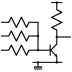
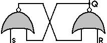
This clipping function is the basis of level restoring logic, and also explains why a two-input device acts as a NOR-gate (the output is already clipped to one of the power rails due to the signal on one of the inputs, and goes no further as a result of the other input). The logic gate depicted here (on the right) is the symbol for a two-input NOR-gate; the transistor circuit shown earlier (above to the right) is the circuit schematic for a three-input NOR-gate. |

|

|
All the other logic gates can be constructed from suitable combinations of NOR-gates. (In some technologies, the multi-input amplifier circuit functions as a NAND-gate. In this technology, all the other logic gates can be constructed from suitable combinations of NAND-gates). |
Only four 2-input logic-gates can be packaged together in a fourteen-pin integrated circuit. There are physical limits, therefore, to the size of the digital circuit (measured in number of logic gates) that can be built this way.
In any case, these days, the designer generally designs circuits on CAD software simulators, rather than directly in the hardware. The output from these simulators is a computer file for driving the integrated circuit layout and electronics production equipment.
At the low scale, this might mean assembling logic gates on a printed circuit board. At a higher scale, it would mean assembling logic gates on an integrated circuit. FPGA (field programmable gate arrays) achieve this by providing the standard logic gates laid out in vast arrays over the integrated circuit, with the CAD software merely supplying the instructions on how to connect them on the final layer of metal interconnect.
Ultimately, though, the output from the CAD software to be implemented on a full ASIC (application-specific integrated circuit). That is, an integrated circuit that performs the specific function that the customer specified.
You could think of an FPGA as the final product of the hardware equivalent of a non-optimising compiler, and an ASIC as the output of an optimising hardware compiler.
Between the two extremes of standard logic gate devices (that can be used for any digital circuitry) and an ASIC (that can be used for one job only), there are the Application Specific Standard Products (ASSP); that is, standard devices for an application-specific area.
Indeed, ASIC is a slippery term. If a company has a design for an integrated circuit, for use in its own products, and gets a fabrication plant to make a million of them, they would indeed be termed ASICs. But if that company instead choses to advertise them, and sell them to end users, for use in their products, they would probably be termed ASSPs.
This class of integrated circuit includes all the line drivers, bus controllers, motor controllers, and power regulators that are described in this document, plus many, many others.
Memory
To the user, there is only one type of computer memory. All memory is equal. For the past decades, though, computer engineers have had to balance the advantages and disadvantages of including differing amounts of expensive fast memory, and cheap slow memory. This is the main distinction between the various types (SRAM, DRAM, EEPROM, flash memory, and the rest). There is also a difference in cost that results from choosing memory that is writeable or read-only, and volatile or non-volatile (whether the data disappears or stays when the power is turned off).
|
A flip-flop can be made using two NOR-gates connected together, and can store a single bit of information. This idea can be extended further, with ten NOR-gates connected together, each with ten inputs (one forming an external input, and the other nine connected to the outputs of each of the other NOR-gates). Such a unit would be capable of being placed in one of ten states, and hence capable of storing a base-10 digit (and similarly for any other number base). |
|
A register consists of one flip-flop for each bit in the word, and hence can store a complete integer, or a complete word of information. As an aside, since a base-N storage cell consists of N NOR-gates, and each NOR-gate can be implemented using a single transistor or triode, plus a few resistors, it follows that the cost of a cell to store a digit in base-N is proportional to N. But, in order to store a set of integers, whose biggest is MAXINT, it would require logN(MAXINT) such cells for each integer to be stored. So the cost, C, for storing each integer is of the order of k.N/ln(N), where k is a constant, equal to ln(MAXINT). This reaches a minimum when dC/dN is zero, which occurs at N=e=2.7. Thus, base-2 or base-3 are both fairly close to being the most efficient bases for storing integers, with base-2 being preferred since it fits in so well with the logic that is being used to implement it (the NOR-gates that make up the base-N meemory cell use binary logic signals, for example). This was the reasoning in the 1950s, when the cost of resistors was neglible to that of transistors or triodes. With integrated circuits, though, the cost of a resistor is equal to that of a transistor, and the cost per integer stored becomes proportional, instead, to k.N2/ln(N), or more precisely to k.(N+2)2/ln(N), and has a minimum around N=√e=1.64, thus confirming further the choice of base-2 as the best number base to use. |

|
Static-RAM (SRAM) consists of a large number of such binary registers (as many as the word-capacity of the memory device). This type of memory is static inasmuch that the information will remain intact indefinitely in the memory (so long as the power remains connected).
Since energy can be stored in electric fields and magnetic fields, and hence in capacitors and inductors, so too can bits of information. A dynamic-RAM cell (DRAM) consists of a single logic gate plus a capacitor (and hence is about half the size of an SRAM cell, and hence roughly twice as much memory can be placed on a given area of silicon). However, the energy, and hence the information, gradually leaks out of the capacitor over time. Consequently, each cell of the DRAM needs to be refreshed periodically, with the information being read, amplified, and written back into the capacitor. This is the sense in which this type of memory is dynamic.
EEPROM and flash memory are a type of DRAM in which the capacitor is implemented as a transistor gate electrode buried below a protective layer of SiO2. The energy, and hence the information, still leaks away, but not significantly for several decades. So, although definitely related to DRAM, these two types of memory are considered to be non-volatile memory (that is, memory that keeps its information even when the power supply is turned off).

|
For normal memory, only one word of memory can be read (or written) at a time. To organise this, the memory array is also connected to an address bus. Each word in the memory is kept silent except for the one that responds to a unique pattern of bits on the address bus. (This one is said to be gated through to the data bus, using one AND-gate for each bit of the word). Simplistically, a 16-bit address bus could be decoded using 65536 sixteen-input AND-gates, each one preceded by a unique combination of inverters on some of the inputs. In practice, the address decoder section can be implemented more economically than this, using a tree of AND-gates. It is the address decoder that allows the RAM to be random-access: that is, just by changing a few bits of the address bus, the memory can change from gating through a word from one part of its array, to gating through a word from any other part. |
Dual-port memory allows two words to be accessed at a time, and understandably involves more logic in each word of the device. This is used particularly when it is necessary to be able to continue to read words from the memory while another word is still in the process of being written.
A memory device can be thought of as a hardware function that takes a single parameter (on the address bus) and returns a single result (on the data bus). Content addressable memory (CAM) performs the inverse function. It takes the contents of the data bus as the input parameter, and returns the appropriate reference, on the address bus for example, as its result. Again, this involves a significant increase in the amount of logic in each word of the device.
Even cheaper than semiconductor memory are the types that tend, instead, to be referred to as data-storage. These are usually magnetic (tape, hard disk, floppy disk) or optic (CD-ROM, DVD-ROM) in nature. All of them are types of long-lived (non-volatile) dynamic memory, and tend to be sequential-access memory (SAM), rather than random-access memory (RAM), inasmuch that having accessed one word, the most convenient word to access next is the one that happens to be next passing under the read-head of the unit.
Smart-cards and Memory-cards
The major function of memory-cards is still memory. Smart-cards are similar, but with encryption and security protection added (hence the need for an internal processor). These are usually used as memory devices for remembering passwords, biometric data, or phonecard or electronic purse balances.
Such cards can be: contact cards or contactless cards.
The contact cards usually have eight electrical contacts. When plugged in to the card reader, two of these are used to supply power to the memory integrated circuit that is embedded in the card, and the others for clocking, address and data signals to get the data into and out of the memory.
A contactless card also has a memory integrated circuit embedded in the card, but instead of being connected to external contact pads, it is connected to a coil of wire that wraps round the flat surface of the card. This coil acts as an antenna for data signals, and as one coil of a transformer for the power supply to the integrated circuit. The card reader carries the other coil of the transformer, which also doubles up as the other antenna for data transfer.
Transferring address and data bits from the reader unit to the card is fairly straightforward. The address and data bits are modulated on the carrier frequency that is already being used for the power transfer. Transferring data bits from the card back to the reader, during a memory read operation, is achieved by the circuitry on the card applying a short-circuit connection across its coil as a means of encoding the data bits. The reader unit can detect the changes in impedance of the transformer that are caused by the secondary coil having been shorted, or left open circuit, in the same way that the coil of a metal-detector can find metal objects buried in the sand on the beach.
A contactless memory-card is generally called a radio frequency identification tag (RFID). These are increasingly being used as replacements for bar codes. (They are more expensive than a bar code printed on adhesive paper, but are more easily detected electronically, and can have their contents changed electronically).
Real Time Clocks and Supervisors
Real time clocks (RTC) and supervisor circuits are generally implemented as integrated circuits that sit beside the microprocessor. The former are true peripheral devices, with memory as their principle function (a real-time clock needs to remember the current time so as to be able to increment it at the next clock pulse). The latter, though, have a simple control function (as described next), but the two tend to be manufactured by the same manufacturers, and can even be packaged in the same device (possibly along with an extra bank of memory).
There are several functions that a microprocessor supervisor can perform, with different models able to perform differing combinations of these functions. One function is to monitor the power supply, and to warn the microprocessor if it has dropped below a certain threshold voltage (at which point the microprocessor can save its critical data to non-volatile memory, and go in to some safe shut-down mode). Another function is not just to warn the microprocessor of a dip in the power supply, but to organise that a battery supply gets switched in cleanly instead (and to be switched out again, when the main supply returns above the threshold voltage). Another function is to monitor the data bus, address bus and/or control bus, and to assert the reset signal of the microprocessor if certain routine conditions are not met within a given period of time. This is the watch-dog timer (WDT) circuit, and is designed to restart the processor if activity seems to have stopped, or if activity seems to be frantic, but stuck in a tight loop.
Processors, Microprocessors (MPUs), Microcontrollers (MCUs), Digital Signal Processors (DSPs)
A processor is usually a device that executes a stored computer program, applying it to a stream of incoming digital data.
All computers contain units for performing the three following major functions: processing, memory, and input/output communications. Even the experimental attempts to break away from the standard computer architecture, in the 1980s, still involved these three functions.
It is beyond the scope of this document to describe the construction of a current standard processor. Instead, the construction of a highly simplified processor (the MAL1) is undertaken, to give an idea of what a more elaborate design might involve.
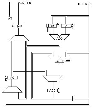
Let us assume that the data bus is 16 bits wide, as is the address bus. (This is very conservative by today's standards, but it would have made quite a reasonable microprocessor up to the 1980s). Let us assume that the memory, therefore, is 16 bits wide, as are the registers within the processor.
The simple processor might consist of five main registers: the program counter (PC), the accumulator (ACC), the instruction register (IR), the index register (X), and the memory address register (MAR). All of these will have been cleared (to zero) by the reset signal to the processor.
The instruction cycle might consist of the following sequence of six simple machine cycles:
|
|
The instruction cycle is repeated over and over, each time fetching an instruction from the next successive word of memory (because of the increment to PC that occurs in the third machine cycle).
The interesting work is done in the sixth machine cycle. Four out of the eight instructions cause new contents to be latched into the accumulator (the ROR, COM, ADD and BIC instructions respectively cause ACC to be loaded with: the data from the data bus rotated one bit to the right, the bitwise complement of the data from the data bus, the result of adding the data from the data bus to the previous contents of ACC, the result of bitwise-clearing the data from the data bus into the previous contents of ACC).
Of the other four instructions, IND causes the contents of the data bus to be latched into X; and STR causes the output of ACC to be routed to the data bus, and the write signal to be sent to the memory instead of read. JMS causes the output of PC to be latched into the input of ACC, and the contents of the data bus to be latched into the input of PC. Lastly, the DCS instruction causes the output of ACC to be routed through the ALU as usual, to be decremented, and the result to be latched back into the input of ACC, and the contents of the address bus to be latched into PC if the new value in ACC is not zero.
The logic involved in decoding the instructions, (JMS=000, STR=001, IND=010, BIC=011, ROR=100, COM=101, ADD=110 and DCS=111) has not been shown, but is fairly simple and straightforward.
| 0: | JMS adrs | Jump (indirect) to Subroutine |
|---|---|---|
| 1: | STR adrs | Store ACC at (Adrs) |
| 2: | IND adrs | Index on (Adrs) |
| 3: | BIC adrs | Bit-clear (Adrs) into ACC |
| 4: | ROR adrs | Load right-rotation of (Adrs) into ACC |
| 5: | COM adrs | Load 2s complement of (Adrs) into ACC |
| 6: | ADD adrs | Add (Adrs) into ACC |
| 7: | DCS adrs | Decrement ACC and jump to Adrs if not zero |
Each of the simplest registers (MAR, IR and X) consists of 16 flip-flops, each of which might consist of four 2-input NOR-gates (two gates for the flip-flop itself, and two to organise the correct moment for latching new data in). For this, each logic gate might consist of a transistor and three resistors. The other two registers are marginally more complicated, with the bit-clear input for ACC, and the increment function (and a master-slave action) for PC. A full-adder might require nine 2-input NOR-gates for each bit. Multiplexers are needed wherever a register can be fed by one of two sources (such as MAR in the first and fourth machine cycles); this might require three 2-input NOR gates for each bit. Lastly, control logic is needed for decoding the instructions, and other assorted housekeeping jobs. This amounts to about 1600 transistors, and 4900 resistors. If this is implemented on an integrated circuit, the resistors are replaced by partially conducting transistors, so making 6500 transistors in total.
A Pentium 4 processor has 125 million transistors; so one major difference between the two processors is certainly that of scale (about 20000:1). There are many ways in which current processors are different to the simple one described here:
- The data and address buses are wider than 16 bits
- The instruction set has much more than eight instructions
- Floating point operations are supported, as well as integer ones
- The instructions are pipelined. That is, the first machine cycle of the next instruction is able to start long before the last machine cycle of the previous instruction has finished. Indeed, with an instruction cycle that consists of six machine cycles, we might hope for six instructions to be in adjacent states of execution, simultaneously in the pipeline. This, though, leads to a whole host of added complexity to deal with temporary results, and unexpected branch points in the computer program
- The usual memory hierarchy is supported, allowing for multiple levels of instruction cache and data cache, paged memory, virtual memory, and other memory management functions, as well as substantial arrays of some of the memory itself
Computer program
By way of analogy, consider that there is a sort of little chap seated inside the computer. (Traditionally, he is called TOM, the Totally Obedient Moron). The programmer comes along, and feeds in a list of instructions that are to be executed in strict sequence, without question. For example:
1: Ask me for a value for A
2: Ask me for a value for B
3: Copy the value of the remainder of the division of A by B as a new value in R
4: Copy the current value of B as the new value in A
5: Copy the current value of R as the new value in B
6: If B is greater than 0, go back to step 3, and continue executing from there
7: Tell me what the value is in A
8: Stop
On executing this, TOM will first ask for two values (the programmer could supply the values 33932 and 68034, for example) and would then go into a loop, executing steps 3, 4, 5 and 6 several times, before replying with the value in A (34, in this case).
TOM really is the perfect Totally Obedient Moron to the extent that he/she/it will execute statements in a loop, such as 3, 4, 5 and 6 in the example, indefinitely, without ever questioning the wisdom of continuing.
The above program is based on Euclid's algorithm for computing the highest common factor (HCF) of two integers. The previous section considered how to implement some of these steps in processor hardware. Already steps 1, 2, 4, 5, 7 and 8 should be self-evidently tractable, only involving the latching across of binary numbers from one register of flip-flops to another. That just leaves steps 3 and 6, which turn out to be relatively straightforward to implement in hardware, too. In effect, the above program is written in the makings of a high level programming language, so steps 3 and 5 each need to be implemented in a large number of assembler level language instructions, of the type indicated in the previous section (a translation job that is usually performed by a computer program called a compiler).
Peripheral Line-drivers, Bus Controllers, Network Controllers
Peripheral devices (like keyboards, displays and printers) count more as self-contained equipment, worthy of a complete page (at least) devoted to each. Therefore, they are not described further here. However, the interfaces and interconnections can be briefly introduced here.
|
|
A microprocessor is designed to use the minimum power possible (not so much for ecological reasons, but for the more pragmatic problem of how to dissipate all that power finally as heat). Consequently, it is incapable of generating the signals for a keyboard or display a couple of metres away, or for a printer tens of metres away. The signals from the microprocessor need to be amplified. This type of amplifier is called a driver. Drivers exist for all sorts of equipment (motor drivers, fluorescent lamp drivers, etc.). In this particular case, the devices are classified as line drivers, and often need to be bi-directional. |

|
Also in short supply on a microprocessor are external connectors. Inputs and outputs tend to be shared many times over, distinguished by context (such as the state of a set of control signals, or the state of the address bus). The peripheral driver needs some logic to be able to decode these signals. In extreme cases, the amount of external processing that is involved can justify the device being called a controller, rather than a driver.
Computer buses are the long-haul freeways for the data inside the computer box, and are generally organised in a hierarchy of buses from slow peripheral devices feeding into faster ones, as the data travels in towards the central processor (and vice versa as it travels out from it). The buses themselves, and the bridges between them, involve such complicated controllers that they almost qualify as processors in their own rights.
Once outside the box of the computer itself, data is routed around office buildings on a local area network (LAN), or wider afield on a wide area network (WAN). The ultimate network, of course, is the international telephone network. Consequently, controllers for all sorts of communications (copper cables, optical fibres, radio links, satellite links) are possible, plus bridges between two similar networks, and gateways between dissimilar ones (note, though, that they are both called bridges when applied to buses inside the computer's box).
For many sophisticated network protocols, there are several layers of control that the information has to pass through when entering or leaving the network. The circuitry that is closest to the physical bus (to the copper track, the fibre cable, the radio antenna) consists of the driver amplifiers and control logic that deals with the voltage levels, the modulation of carrier waves, the pulse widths, and the handshaking between the signals. Further back, there is circuitry for dealing with more abstract concepts, like address headers on data packets. Even further back, there is circuitry for dealing with even more abstract issues, such as accessing pages of information. The ultimate level is driven by the human user (generating the speech data, for example), or by the microprocessor executing through a complex algorithm on the user's behalf. In the IBM/OSI system network architecture (SNA), seven layers are thus identified, with the physical layer at the bottom, and six increasing levels of abstraction above that (datalink, network, transport, session, presentation, application).
|
Modulation was mentioned as a low-level, physical-layer operation. This is a set of techniques that have been used in electronics since the early days of radio transmission. Audio frequencies, from the studio microphones for example, can be superimposed on the radio frequency signal. In this way, the audio information is encoded on to the radio signal, where it is more convenient to transmit and to handle. Similar techniques are used to encode audio information on magnetic tapes. The illustration, for example, shows a high frequency sine wave whose amplitude varies according to a low frequency sine wave (amplitude modulation, AM). The receiver needs to be able to extract the audio information again from the radio signal, and does this in a process called demodulation. |

|
In the case of digital signals being transmitted on a telephone line, the modulation process is much the same, but would give a more abrupt variation, for amplitude modulation, than the gentle sine wave shown in the illustration. The carrier frequency would only be a high audio frequency that is acceptable to the telephone line, and the data rate would have to be at a frequency below this.
There are other types of modulation possible (frequency modulation, FM; phase modulation, PM; pulse width modulation, PWM). And there are various encoding schemes for getting the maximum amount of information into the available bandwidth.
Since the data transfer tends to be bidirectional, the operation is performed in a unit that performs both functions, as appropriate. A modem unit is a modulator-demodulator unit.
Similarly, at the next layer of the hierarchy, a unit that transmits digital data will probably also need to be bi-directional. Again, the two functions might be incorporated in a single unit. A transceiver is a transmitter-receiver unit.
In the days before push-button, digital telephones, communications links were set up in a configuration called circuit switching. That is, during the dialling operation, each of the intermediate relay stations would set up a chain of links between the sender and the receiver of the call, and this would be maintained throughout the duration of the call. Now, though, digital telephone networks generally use packet switching, instead, which is the electronic-data equivalent of the postal service (working a much higher speed, of course). In this, the data are gathered together as a packet of information, and the destination information is appended (in effect, the telephone number is treated as an address on the outer envelope of the data packet). The complete packet of data is passed over to the next relay station that is closer to the destination, and the connection behind it is released. Any subsequent data, or indeed any reply data, is similarly packaged up, and submitted to the nearest relay node, where it does not necessarily end up taking the same route through the network as the first packet did.
Circuit Board Sockets and Integrated Circuit Packaging
In theory, any electronic device could be plugged in to a socket, where it is the socket that is soldered to the circuit board, not the device. In practice, since the socket costs money, takes up space, and involves an extra assembly step, devices are normally soldered directly to the circuit board, with only the most expensive, or those most likely to need to be replaced in the field, placed in sockets. This judgement, of course, is relative and context dependent. Consequently, all devices are designed primarily to be soldered directly to the board, and any sockets are designed for making mechanical/electrical connection to the solder points on the electronic device (usually pins, but possibly tabs or balls).
Since integrated circuits are produced in a huge variety of different format packages, so too are their corresponding sockets. Typical examples are:
- Single in-line package (SIP), with all the pins along one side of the package
- Dual in-line package (DIP), with all the pins along two parallel sides of the package, and often differentiated further according to the packaging material, such as plastic (PDIP) or ceramic (CDIP)
- Quad flat-pack (QFP), with all the pins along four sides of the package, and often differentiated further with prefixes like "thin" (TQFP) to indicate a device that lies very low on the circuit board
- Small-outline (SO or SOIC), which is like DIP, but designed for surface-mount soldering (surface mount technology, SMT, or surface mount devices, SMD) rather than through-hole for DIP. The prefix "thin" can be added when appropriate, and the material, like plastic, can be added as a postfix, for example as TSOP (thin small-outline plastic)
- TSSOP (thin-shrink small-outline plastic), and a whole host of other combinations
- Plastic leadless chip carrier (PLCC), with all the pins along four sides of the package, but curled in under the device
- Pin grid array (PGA), with the pins all over the bottom surface of the package, arranged as a matrix
- Ball grid array (BGA) is more common than PGA, and is effectively the surface mount equivalent, using solder balls arranged in a matrix on the underside of the device.
Hardware and Software Tools
As well as needing soldering irons, pliers, screw-drivers, the designer of a prototype circuit needs CAD software for electronics and microelectronics design, such as digital logic simulators, analogue circuit simulators, microelectronics placement and routing tools, PCB placement and routing tools, microelectronics mask generators, PCB wiring schedule generators.
Also, hardware development kits, which consist of a board of electronics that the engineer can modify, and experiment with, to investigate various proposals for his own application. Variations of these are also called hardware evaluation kits, and hardware starter kits.
In-circuit emulators (ICE) use a computer to replace a key component (usually the microprocessor or microcontroller) on the engineer's circuit board. This is achieved by taking the key component out of its integrated circuit socket, and plugging the ICE's probes in, in its place. By running the emulator program for the replaced device on the computer, the board functions exactly as if it still had the microprocessor connected in the socket. The emulator program, though, is able to perform in-circuit debugging, by keeping detailed logs of all the traffic on the external probe pins, and allowing experiments to be performed by injecting various signals or unusual behaviour into the operation of the board.
In-circuit debuggers just perform the monitoring function, without necessarily emulating the device itself. This might be achieved by clipping the probes of the debugger on to the pins of the device that is under investigation (or else unplugging the device from its integrated circuit socket, and plugging it into an adapter socket that acts as the debugger's probe, which in turn is plugged into the integrated circuit socket on the board.
Programmers for non-volatile memory (EPROM, EEPROM, flash memory) allow new contents to be stored in a memory device (either committing a new device for the first time, or over-writing any old contents in the case of EEPROM or flash memory). Erasers exist for EPROM, often using ultra-violet light, allowing the old contents to be erased before the device is programmed again.
In-circuit programmers allow the programming to be performed without removing the memory devices from the board. Indeed, the memory might even be embedded within certain processor or controller devices. The programmer achieves this feat by taking charge of the conventional address and data buses.
Multimeters are electrical/electronic measurement instruments for taking static measurements of voltage or current. They usually also measure resistance, and perhaps even capacitance and inductance.
Oscilloscopes, spectrum analyzers, signal generators are analog electronic test and measurement instruments working dynamically, in the time domain. For instance, the oscilloscope is normally used to plot voltage measurements against time. Digital logic analyzers, communication network analyzers are digital electronic test and measurement instruments also working dynamically, in the time domain. For instance, the logic analyzer is normally used to record changes to address and data lines over time. Usually, they can handle multibit buses as a single unit (using a suitable binary notation, such as hexadecimal).
From the system's point of view, printers, recorders and dataloggers are like write-only memory. From the user's point of view, too, the three types of machine are very similar, taking in a stream of electrical readings, and storing them on paper, magnetic tape, computer disk, or some other storage medium.
Machines for Electronics Production
The best way to list the major pieces of capital equipment for doing microelectronics and electronics production-line assembly is to step though the (simplified) production processes.
Wafer Production
Here is a summary of the steps involved in manufacturing blank wafers:
- The starting material is sand (SiO2)
- This is melted at about 1200°C (just as for the production of glass)
- It is then reduced to silicon (still molten)
- It is allowed to crystallize, starting from a seed crystal that is inserted into the pool, and gradually drawn out
- As the growing crystal is drawn out, it forms a cylindrical ingot, or boule, not unlike a very thick candle being formed from molten wax
- Over the decades, the diameter of the ingot has been increased from 1 inch, to 3 inches, to 4 inches, to 6 inches, to 8 inches, and now to 12 inches.
- The ingot is purified further (by zone refining, for instance)
- The ingot is sliced, using diamond-tipped saws, to yield the blank wafers, less than a millimetre thick.
- The wafer is polished on one side, and left smooth (lapped) but raw on the other
- Very quickly, the surface layer of the silicon oxidises, to leave the pure silicon coated in a protective layer of glass (SiO2)
Microelectronics Front-end
Here is a summary of the steps involved in microelectronics fabrication (front-end wafer fab):
- The wafer is placed on a spinning turntable, with the polished-side uppermost, and photoresist fluid is dripped onto the centre. This spreads out in a thin, even layer.
- The wafer is cured (dried) to set the photoresist.
- The wafer is exposed to light shining through a patterned mask, not unlike a photographic enlarger shining light through a photographic negative on to photographic paper. (These days optics can be used, though originally the process was 1:1 without any optics. Also, these days, the light is ultraviolet since the pattern on the mask contains lines whose widths are comparable to wavelength of visible light).
- The photoresist-coated wafer is placed in a bath of solvent to remove the parts of the photoresist that are still soft, leaving the parts that have been hardened by exposure to the ultraviolet light.
- The wafer is placed in an acid bath, which etches the protective SiO2 where there is no longer any photoresist.
- The remaining (hardened) photoresist is stripped off
- A whole batch of similar wafers is placed in a boat, somewhat resembling a toast rack, and the whole batch is inserted into the tube of a diffusion furnace. Here, the wafers are heated to around 1000°C, in an atmosphere of a suitable gas (containing a group-III or group-V element). Gradually, atoms from the gas diffuse into the exposed silicon, where there are gaps in the glass layer.
- The batch of wafers is removed from the furnace, and allowed to form a protective oxide layer again over the regions of exposed silicon.
Each wafer is now ready to go round the entire cycle again, to deposit atoms of a second element in a different pattern. Indeed, the cycle is repeated perhaps dozens of times, with a different mask pattern each time.
Notice that this implies that each new pattern must be aligned with the preceding patterns to an accuracy of less than the wavelength of visible light, over the entire length of each integrated circuit die.
The later patterns involve the deposition of conductive layers of aluminium, that are selectively etched away to form the wiring of the integrated circuit, connecting between the electrodes of the transistors that have been formed in the underlying silicon.
These days, the diffusion step is often replaced by ion-implantation. This involves placing the wafer in a vacuum chamber, and firing ions at it of the desired element (usually the group-III or group-V atoms mentioned earlier).
Microelectronics Back-end
Here is a summary of the steps involved in back-end process of microelectronics fabrication (packaging):
- The wafer is placed in a wafer prober, whose probes connect with each integrated circuit in turn, to test it for correct electrical operation. In the case of a microprocessor or memory, this testing involves running a lengthy test program on each one. Any that fail the test are marked with an ink dot.
- The wafer is scribed between the rows and columns of integrated circuits, using a diamond-tipped scribe.
- The wafer is diced into its individual dice (plural of die), otherwise known as silicon chips.
- The ones with ink dots are thrown away, and the others are put into the integrated circuit packages. The external pins (or balls in the case of a BGA) are wire-bonded to connection pads that have been included in one of the final aluminium layers of the integrated circuit.
Circuit Board Production
Here is a summary of the steps involved in circuit board production:
- The printed circuit board (PCB) starts off as a rectangle of insulator, such as fibre glass, coated with a layer of copper
- The copper is coated with a protective film, and the film is then selectively removed according to the desired wiring pattern.
- The board is dipped in an acid bath to etch away the copper where it is exposed.
- The remaining film is removed, to reveal the unetched copper track
- The simplest boards consist of a single or double layer of copper, but multilayer sandwiches with copper track inside each sandwich, are also routinely produced.
- The board is dipped into a bath of molten solder (a Pb-Sn alloy, though this is now being replaced by lead-free solder), which alloys to the copper track (thereby tinning the copper track).
- The electronic components are placed on the circuit board. In the case of surface mount devices (SMD) they are placed on their connection pads; in the case of though-hole devices, they are placed on the board with the leads or pins poking through the holes that have been previously drilled in the circuit board.
- The circuit board is held just above the surface of a bath of molten solder. A wave is set in motion along the bath, which causes molten solder (at about 250°C) to reflow over the copper track and component connections. Where two metal surfaces are in contact (the copper track and the component leads), some of the solder remains behind after the wave has passed, held back by capillary pressure.
- The board is given a final protective coating (traditionally green in colour).
Power Supplies
A power supply unit (PSU) is a self-contained piece of equipment, but is often found as a major module within a larger piece of equipment.
AC-DC Power Supplies
Several components make up a power supply unit (PSU):
Electrical power is generally supplied as an alternating voltage of over 100V (such as 220V or 110V) at 50Hz (or 60Hz). Electrical power is generally consumed by electronics equipment at a constant (DC) low voltage (such as 5V or 9V or 12V), just as it would expect from a corresponding battery supply.
There are three jobs performed in the PSU:
- A transformer is used to change the hundreds of volts AC down to a few volts AC
- A rectifier is used to change the few volts AC to a few volts DC
- A regulator is used to change the raw few volts DC into a smooth, unfluctuating few volts DC. (This can be achieved with a few discrete components, or these days with PSU regulator and PSU controller integrated circuits.)
A power supply unit for electronics equipment is generally called a PSU. However, a power supply unit for a factory or a railway network might be called a transformer unit, or a rectifier unit or a regulator unit. But note, that this is not the same as a transformer, a rectifier, or a regulator, which are the names of the principle components within those units. (Other domains also suffer from this effect; for instance, a voltmeter can be a simple electro-mechanical device with a dial, or it can be a complicated box of electronics with one of these as its principle component.)
DC-AC Power Supplies: Inverters
Since, in the vast majority of cases, power supplies take AC power from the mains, and convert it to DC power for electrical and electronic equipment, this process is taken as the norm. The inverse process, of taking DC to generate AC power (to power an electric razor from a car battery, or to generate an emergency supply for an office from battery banks), therefore involves an inverter.
DC-DC Power Supplies: Converters and Regulators
The regulator is one of the components that make up a power supply unit (PSU). It takes the low voltage DC output from the rectifier, with all the voltage ripples, and outputs a much smoother DC voltage, perhaps a few volts below the original level.
Having obtained a smooth DC supply for the electronic equipment, it might later be found necessary to plug in a new module that needs a DC supply at a different voltage. One way of achieving this would be to install a second power supply. Another way is to take the existing DC voltage, and use it to generate the second voltage supply.
A step-up DC converter takes one DC voltage supply to generate a second DC supply at a higher voltage. A step-down DC converter (or buck regulator) takes one DC voltage supply to generate a second DC supply at a lower voltage.
AC-AC Power Supplies: AC Conditioners and Filters
The transformer is the most obvious system that takes an AC supply as its input to generate a second AC supply at its output. This leads to an AC supply at the same frequency, but with a different voltage swing (possibly a higher voltage, but more commonly a lower one).
It would not be impossible to conceive of a need for an AC-to-AC power supply that changes the frequency.
Low-pass filtering, such as to suppress RF interference, could be considered, too. Phase correction, too, which is sometimes needed because of the way that reactances cause the AC voltage and current to vary out of phase (inductors cause it to be changed one way, and capacitors cause it to be changed the opposite way). The typical problem area occurs with the use of mains power to drive large motors in a factory environment. Since the motors present a large inductance to the mains supply, it is necessary to put capacitor banks in the circuit to bring the phase change back to zero degrees again.
Battery cells and electrolysis

|
Battery cells allow a chemical reaction to take place with the two reagents separated into separate chambers. Dropping a pellet of zinc into a beaker of copper sulphate solution, for example, will start a chemical reaction: the copper will give up its place to the zinc (the zinc is more reactive than the copper) and will end up with bits of copper deposited on the zinc pellets, and patches of zinc sulphate polluting the copper sulphate solution. So, the revised approach is to have two beakers, one with a zinc electrode in zinc sulphate solution, and the other with a copper electrode in copper sulphate solution, and to connect electric wiring (and perhaps a lamp bulb, a switch, and an ammeter) between the two electrodes. Nothing happens, until some sort of a bridge is made between the two beakers. Traditionally, an upside-down U-tube full of a neutral solution, such as potassium sulphate, is used. (In a commercial battery cell, it is usually even more blatant, with the two solutions placed in the same vessel, but with a selective membrane to keep them from mixing.) |
A tug-of-war now ensues, over ownership of the sulphate ions in the three solutions. As mentioned earlier, the zinc in the zinc electrode is the one that pulls harder, with its atoms trying to go in to the zinc sulphate solution. They can only do so if each one gives up two electrons, which it does on the electrode.
Originally, the solution was balanced, with one zinc ion for each sulphate ion, but now there are starting to be too many zinc ions in the solution. The balance is restored by extra sulphate ions arriving from the bridge. But now, there are too few sulphate ions in the bridge (originally, they had been balanced with two potassium ions per sulphate ion). So, the necessary number of sulphate ions is dragged out of the copper sulphate solution to compensate. But now, there are too many copper ions for the number of sulphate ions in that beaker, so those copper ions try to leave the solution. The easiest place to do this is at the electrode, because this is where there are supplies of electrons to be grabbed by the copper ions to convert them from ions to atoms.
This means that, for the electric circuit, there is a negative charge at one end (lots of electrons arriving on the zinc electrode) and positive at the other end (lots of electrons being drawn off by the incoming copper atoms). With the switch open, the charges build up, and gradually the reactions at the two electrodes come to a halt. In the electrolyte, the chemical reaction tries to go ahead as if it were an ordinary chemical reaction, but with the switch open, the two electrodes become negatively/positively charged. This acts as a brake on further ions following in the footsteps of their predecessors. Even if the next lot do go ahead, that causes the electrodes to become charged even further, so more repulsive of further ions following suit. So, one way or another, the chemical reaction comes to a halt. If the switch is closed, the electrons are able to be repelled from the negatively charged electrode, passing through the lamp and ammeter, and to arrive at the other electrode to neutralise a corresponding amount of positive charge. The electrodes are now less charged, so the brakes come off, and the chemical reaction goes back to continuing in the electrolyte.
What this has done is to take the chemical reaction, CuSO4+Zn→ZnSO4+Cu, and split it in two. In so doing, the flow of the reaction can be controlled with a simple electrical switch, and be made to supply electricity into the bargain.
What if the three electrolytes are changed to zinc nitrate, potassium nitrate, and copper nitrate? Or perhaps to zinc chloride, potassium chloride, and copper chloride? The battery cell would still work, but this does not mean that the choice of electrolytes is unimportant. Instead, it means that we happen to have found that the two reactions, CuNO3+Zn→ZnNO3+Cu and CuCl2+Zn→ZnCl2+Cu are also valid reactions.
The chemists discovered they could do this with just about any chemical reaction. So a fuel cell even allows CH4+3O2→CO2+2H2O to be split in two, and to release the energy as electricity (instead of as heat in a conventional flame of burning methane).
Electrolysis is what happens when the electric circuit pushes the reaction backwards (so depositing zinc back on the zinc electrode, at the cost of dissolving copper from the copper electrode). If a battery cell is just a manifestation of an exothermic chemical reaction made to take place split across two chambers, via the intermediary of an electric circuit, then�electrolysis is just a manifestation of an endothermic chemical reaction made to take place split across two chambers, via the intermediary of an electric circuit. In order to do this, the electric circuit needs to push harder than the electrolysis cell is pushing in the other direction. This could be achieved using a battery with even more reactive metals than the ones in the electrolysis cell, or else by paying for the services of a nearby nuclear power station (the endothermic reaction is driven by the flame in a gas-fired power station, say, instead of by the more usual bunsen burner flame). It is all just one tug-of-war nested inside another (one tug of war over sulphate ions, then another over direction of electron flow) all under the auspices of the second law of thermodynamics.
Batteries versus Electrolytic Capacitors
What is the difference between a rechargeable battery cell and an electrolytic capacitor? They are both used to store electrical energy for later use. In both cases, the device consists of two electrodes immersed in an electrolyte, with the charge cycle involving the removal of a large number of electrons from one electrode plate, accompanied by the adding of the same number to the other. When multiplied by the charge on each electron, this quantity gives the amount of electrical charge, measured in coulombs (or ampere-hours, which are just coloumbs times 3600). In so doing, a voltage difference builds up between the two electrodes (Q=CV).
The difference is that the capacitor is designed to be linear, so that the voltage is directly proportional to the amount of charge (with the constant of proportionality given by the capacitance of the device, Q=C.V); while the rechargeable cell is designed to be flat, with the voltage held constant, and hence with the capacitance varying in direct proportion to the amount of charge (with the constant of proportionality given by the constant voltage, Q=V.C). Indeed, a true capacitor does not use an electrolyte, but a passive dielectric insulator; the voltage between the plates is naturally proportional to the charge on the plates. A battery cell achieves the storage of greater amounts of charge through a chemical change between the plates and the electrolyte, and this also achieves the effect of keeping the voltage between them fairly constant (based on the chemical properties of the plates and electrolyte). The electrolytic capacitor benefits from the greater charge storage of the electrolyte mechanism while still having nearly the linear voltage to charge relationship of a true capacitor.
This difference is also seen when comparing their behaviours over time, with each connected to a resistive load, having first charged each of them with the same electrical charge, to the same voltage. The ideal electrolytic capacitor, keeping C constant, will have a voltage that decays exponentially, V.exp(-t/(RC)), so that by time τ (=RC), the voltage will be down to 1/2.718th of its original level, and will continue to fall exponentially from there onwards. The ideal rechargeable cell will, instead, keep a constant voltage as the charge flows out, finally dropping to zero, in a step function, after the same time, τ (=RQ/V).
The final dropping to zero, of course, is unavoidable. No cell can store an infinite amount of electrical energy. The capacitor has a maximum voltage rating, before the dielectric breaks down; and the battery cell has a maximum capacity, ultimately because it must be limited to a finite mass (as given by E=mc2). Of course, we are presently far from this extreme, and the reason that we never notice this extra mass in normal batteries is that even for a 50 ampere-hour 12V car battery consists of material weighing about 18kg, plus energy that adds only about 2.4x10⁻¹² kg to this.
Motors

|
This part of the document is written as a brief summary of the different types of electric motor, to give a short description of the distinction between their various types. Although it is possible to make an electric motor that use electric fields (or indeed any energy field), the vast majority, in fact, all use magnetic fields. |
The idea common to all of these motors is that if a magnetic north pole on the rotor is part way between a north and a south pole on the stator, it will tend to rotate repulsively away from the north pole, and attractively towards the south pole.
Some means most then be found to keep the rotor and stator from finding an equilibrium position, by arranging that at least one of the magnetic fields keeps changing.
One way of achieving this is for an AC supply to be applied across electromagnets in the stator, and for the permanent magnet in the rotor to be repeatedly attracted and then repelled by each electromagnet.
With a single-phase AC voltage, there can be two electromagnet coils in the stator; with a three-phase supply there can be six (and hence a much smoother, and more powerful cycle).
This would be a brushless synchronous motor since there is no need for electrical brushes to take electric current to the rotor, because the magnets are permanent magnets, and they turn in direct synchrony with the phase changes in the electromagnets of the stator.
Putting the permanent magnets in the stator and the electromagnets in the rotor has the advantage that the weight of the permanent magnets can be increased to allow for stronger ones to be used, without increasing the inertia of the rotor. The AC current is taken to the rotor via two slip rings, with electrical contact made via a brush on each one (made of graphite, copper, or some other suitable material). The motor would still be synchronous.
The next idea would be to put electromagnets in both the rotor and stator. Again, brushes would be needed to supply the current to the rotor. Probably, instead of the slip rings, though, a commutator would be used as a mechanism for keeping the polarity of the rotor magnets opposed to that of the stator magnets.
When the coils in the rotor periodically align with coils in the stator, it temporarily forms a transformer. This could be a possible method of getting electrical energy to the rotor without using the brushes. I am not aware of any motors exactly of this type, but in its degenerate form, it is effectively the basis of an asynchronous induction motor. In this, the AC field in the stator coils induces an eddy current in that part of the cylindrical metal plate of the rotor that is closest to it (effectively acting as a single turn of the secondary winding of the transformer). This causes it to generate a magnet field that interacts with that from the stator coil. As the rotor rotates, a different part of the metal of the rotor moves under the stator coil, and has an eddy current induced in it. The metal can be copper (for conductivity), or aluminium (for lightness and cheapness), and rather than a plate, can take the form of a cylindrical cage of stout wires.
If the supply is DC, the designer has to organise for the motor to be fed with an AC supply by some type of inverter. This can then be used by any of the types of AC motor already described (asynchronous-brushless, synchronous-brushless, synchronous-brush motors).
A much simpler method, though, is to use a commutator. This has already been described as a means of getting a DC supply to the rotor, when the external supply is AC. Now it is performing the inverse job. This is how the traditional DC motor works, using either permanent or electromagnets in the stator, and electromagnets in the rotor that are kept opposed to those in the stator by reversing the electrical connections every half cycle.
Of course, slip-rings and commutators, along with their brushes, are expensive complications to the design of any electrical motor. They are also wasters of electrical energy, through friction, arcing, and other subtle effects. Much design effort has been expended in attempting to eliminate them. One result is the various types of brushless motor already described. Another result is the design of a whole range of electronic motor controllers. In effect, the DC to AC inverter fits into this family, controlled by an oscillator that sets the target frequency for the AC conversion.
Instead of using a separate oscillator, the signal can be derived by sensors on the drive shaft of the motor itself, such as optical or magnetic sensors, that effectively take over one part of the job that was performed by the commutator. This is the technique that is generally marketed for brushless DC motors
Of course, the DC to AC inverter is not limited to converting to single-phase AC, nor even to three-phase AC. If there are N-phases, the motor can have 2N separate coils in its stator. Moreover, the AC need not be kept going at a constant frequency. Indeed, in the extreme case, the frequency can be reduced right down to zero between periods of faster movement. The idea of a stepper motor is that the rotor should step forward by just one fraction of a cycle, and then stop, awaiting the pulse in the next coil.
Finally, this brings up the subject of how to control a motor. For a synchronous motor, the main control is the frequency of the AC supply. For an asynchronous motor, one possible control involves varying the mean magnitude of the voltage (and hence of the current, too). This works since power equals the product of voltage and current. Indeed, even in the case of a synchronous motor, if the voltage and current are not kept high enough, for the given load that the motor is connected to, it will fail to keep up with the AC field, and will slip.
Furthermore, since motors are highly inductive, and could have voltage and current as much as 90° out of phase, it is possible for a poorly designed motor to have its peak current when the voltage is close to zero, and hence for it to be delivering near to zero power. This is one reason for using phase correction circuitry.
Hydraulic analogy
Water flow is the traditional analogy for helping to visualise how electrical and electronic devices work. Like all analogies, it is only a model, and all models have their limits; the analogy will sometimes break down. We cannot expect, for example, that it will illustrate all of Maxwell's equations, and allow transformers and radio transmitting aerials to be modelled. Keeping this in mind, though, the analogy is one that I personally still find very helpful, even after all these decades since graduating, as a sort of sanity-check on how electronic devices work.
Hydraulic analogue of an Electric wire
A water pipe.
Hydraulic analogue of an Electric voltage
The analogue of electrical voltage is water pressure (force per unit area, where the area is the cross-sectional area of the pipe). Working out its value at all points round a circuit, the analogue of Kirchhoff's voltage law can be seen to apply correctly. This requires the ability always to be able to trace out a complete circuit, which is true if we include the water table as the reference point (the analogy of the earth point) or to the local sump (the analogy of the chassis connection) of the pump, and the point to which all the water in the pipes eventually flows back.
Hydraulic analogue of an Electric current
The analogue of electrical current is water flow (volume per unit time). So, Power=V.I (pressure*volume/second).
Hydraulic analogue of an Electric charge
The analogue of electrical charge is water volume (measured in cubic metres, or fractions thereof). (This begs the question, then, as to whether there is an equivalent inverse-square law that could be concocted for volume.)
Hydraulic analogue of a Soldered connection
The analogue of electrical junction is a T-junction connection of two pipes. The analogue of Kirchhoff's current law applies correctly.
Hydraulic analogue of an On/Off switch
The analogue of electrical single-pole/single-throw switch is a simple Open/Closed valve. [Back to the electrical counterpart.]
Hydraulic analogue of a Diode
The analogue of electrical diode is a one-way valve, such as a one-way ball valve. [Back to the electrical counterpart.]
Hydraulic analogue of a Battery
Treating a battery just something to generate a steady pressure in the water pipe, the hydraulic analogue would just be a water pump that is running continuously. [Back to the electrical counterpart.]
Hydraulic analogue of an AC source
Similarly, to generate the hydraulic analogue of an alternating current, we just need a device that pushes and pulls the water into and back out of the pipe (such as a cylinder and piston arrangement acting like a syringe, driven by a constantly turning motor).
Hydraulic analogue of a Resistor
A long length of narrow diameter pipe (just as the analogue can be made of a long length of narrow guage wire). This correctly obeys R=ρ.l/A (the resistance is proportional to the length of the resistive wire/pipe, and inversely proportional to its cross-sectional area). It also obeys Ohm's Law, V=I.R (to a first approximation). [Back to the electrical counterpart.]
Hydraulic analogue of a Capacitor
A wide water pipe that has a rubber diaphragm across its cross-section. This acts to block the flow of current once the diaphragm has bulged out, and has stretched enough to equalise the pressure difference in the pipe (with the capacity of the bulge to hold a certain volume of fluid being proportional to the pressure, or voltage). However, if the external pressure is made to alternate (between blowing and sucking), a corresponding alternating current will manage to flow through the capacitor, with the diaphragm flexing each way. A capacitor, therefore, impedes a steady flow of current, but is a good conductor of alternating currents.
Just like the dielectric in an electric capacitor, the capacitance is proportional to the stiffness and area of the diaphram, and inversely proportional to its thickness, as in C=ε.A/d, and it correctly models Q=C.V. [Back to the electrical counterpart.]
Hydraulic analogue of a Inductor
The analogy starts to get a bit weak at this point. It is true that a long length of pipe (like a long length of wire) will give some of the effect, for an alternating current, or for a fast flowing current that is suddenly stopped or started, due to the inertia of the water. However, coiling the long length of pipe might be a convenience, but does not give the enhanced effect of a coiled length of insulated wire.
On the plus side, you will, at least, be able to demonstrate RC, RL, LC and RLC circuits and the differential equations for Simple Harmonic Motion. [Back to the electrical counterpart.]
Hydraulic analogue of a Transformer
Just as for the inductor, the analogy fails completely. The effect can contrived, though, using a pair of water wheels that are geared together so that the flow of water in one circuit turns its water wheel, and thereby causes a flow in the other circuit, by the geared turning of its water wheel. This even correctly gives a correct analogue for "V1.I1=V2.I2+losses" (where "pressure" times "volume/second", as the analogues to "voltage" times "current", both amount to saying that the power out is the same as the power in. [Back to the electrical counterpart.]
Hydraulic analogue of a Transistor
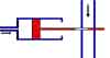
Figure 1. Enhancement Mode Pneumatic Transistor |
The usual analogue of a field effect transistor is a device in which a section of flexible pipe is constricted by the pressure of the water in a surrounding jacket of water supplied by another circuit that pinches the hose so that the water flow is stopped. Then, with just a small reduction of the pinch pressure, a large change can be achieved in the water current that is able to flow. That is, as the pressure (voltage) in this jacket (gate electrode) is increased, so the resistance in the flexible pipe (channel region) is increased from one end of the flexible pipe (the source electrode) to the other (the drain electrode). More refined, Figures 1 and 2 depict devces (enhancement or depletion mode, respectively) where the pressure of the fluid in one pipe controls the flow in a wider one. It is interesting to consider how a hydraulic, or rather a pneumatic, transistor could be considered to be composed, effectively, of steam engine parts. [Back to the electrical counterpart.] |

Figure 2. Depletion Mode Pneumatic Transistor |
Hydraulic analogue of RC and RL filters
Consider a particular garden watering system, with a long thin length of pipe (a conductor with a certain resistance) dipping into a well, connected to the type of storage tank with a diaphragm (a capacitor), with the garden hose coming off at the junction between the two (the load resistor). When the pump is turned on (at the bottom of the well) the water in the pipe flows almost immediately, and starts to fill up the tank. It takes a second or so for the pressure in the tank to build up enough, though, for it to start pushing water down the garden hose. Then, when the pump is turned off, the water stops flowing in the up-pipe from the well almost immediately, but there is still pressure in the storage tank to push water down the garden hose for a few more seconds. Thus, in a R.C configuration like this, the current is out of phase with the voltage, and leads it.
That is one cycle of a square wave A.C. input. Repeat it over and over to see the effect of a square wave (with the pressure causing the flow in the garden hose lagging behind what is happening with the flow in the long up-pipe from the well. A sine wave A.C. input would do something similar, but with a more rounded response. (With a square wave input, the response is a bit triangular, saw-tooth, in shape.)
Conceptually (as a thought exercise, even it it might be difficult to get working in practice) if the storage tank is removed, and the garden hose replaced by a much wider one (still within the capabilities of the pump, and already initially full of water) and the experiment is repeated, an R.L filter is modeled. When the pump is turned on, it will try to start water flowing up the up-pipe from the well, but will find that it has to work against the body of water in the wide pipe (due to its inertia) to try to get it moving. Once moving, things can be pumping smoothly. Then, when the pump is turned off, the body of water in the wide pipe will still be moving under its own inertia, and pulling water up the up-pipe, and through the lifeless pump (like a partial siphon). On measuring the pressure at the junction, it would be found that it is the flow of water in the up-pipe that is now lagging that pressure. [Back to the electrical counterpart.]
Hydraulic analogue of a Zener Diode
In the forward-biased direction, the analogue of electrical Zener diode is the same as for a diode: a one-way valve, such as a one-way ball valve. In the reverse-biased direction, there would need to be a pipe running round the valve, normally blocked by some sort of pressure-release mechanism. Normally, a Zener diode is permanently wired in the reverse-biased direction, with a connection down to ground, and much of this direct modelling detail can be left out; instead, it can be modelled as a water-head (a canister fixed up at a height, with water entering through one pipe at the top, and an outlet pipe at the bottom, and a third pipe at a fixed height in the canister acting as a weir or overflow that vents the surplus water down to the sump. [Back to the electrical counterpart.]
Hydraulic analogue of an electronic circuit
Armed with all this, you can convert any electronic circuit diagram into a plumbing system of water pipes, and analysed using much the same tools. If the electronic circuit diagram is too complex, though, such as that for a computer processor, it certainly will not be micro any more.
Div, Grad and Curl
One illustration of the meaning of Div, Grad and Curl can be gained by considering a tiny water droplet forming inside a cloud. Div gives a measure of how quickly other water molecules are arriving or departing (in each of the directions, x, y and z). Grad gives a measure of forces applied to move the water droplet in any of the directions (x, y, z) such as from convection currents and gravity. Curl gives a measure of the differential forces applied to opposite sides of the droplet (-x and x, -y and y, -z and z) causing it to rotate. This is only an illustration, though. In the case of fields (electric, magnetic, gravity) Div, Grad and Curl are used even though there are no moving particles involved.
Conclusion
This is the end of this brief summary to the terminology used for electronics devices. As stated at the beginning, this document was designed simply as an introduction, and to serve as a base for finding out more about each of the electronic devices.
map